Transition Radiation Tracker (TRT)
The TRT is a large volume charged particle tracking detector with 350,000 readout channels, and is important for the excellent momentum resolution of the ATLAS experiment. Each channel is a straw 4 mm in diameter filled with a Xenon/CO2 gas mixture. There is a 31 micron diameter ground wire at the center and the outer wall of the straw is held at a potential of -1500 Volts. Penn played a leading role in the design of the front-end readout electronics, the commissioning of the detector from 2006-2009. Penn graduate students and postdocs have served as data acquisition (DAQ) and software experts during data-taking in Run 1 (2009-2012) and Run 2 (2015-2018). We’re preparing for operation of the TRT in Run 3 (2021-2024).
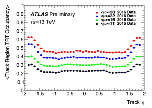
Tracking: A high energy charged particle passes through about 30 straws as it traverses the detector. In each straw, the high energy charged particle ionizes a few of the Xenon atoms, with the ionized electrons moving towards the wire and the ions moving slowly towards the straw wall. In the strong electric field close to the wire, the electrons will cause an avalanche of ionization that significantly amplifies the signal into the femto-Coulomb range. The TRT records the time of arrival of this avalanche of electrons by checking if the signal on the wire is above a low threshold every 3.125 nanoseconds. Each straw provides a 2D measurement of the position of the charged particle with a resolution of about 130 microns. The straws with hits above threshold track the path of the charged particle.
Electron identification: Extremely fast-moving charged particles will shrug off transition radiation as they pass through a foam between the straws. The Xenon gas has a good absorption cross section for this X-ray transition radiation and the resulting ionization signal is 10-100 times larger. Each bunch crossing (every 25 nanoseconds), the TRT records if the signal on the wire is above a high threshold. As the electron is lightest charged particle by a factor of 200, an electron is much more likely to produce transition radiation than a muon or charged pion with the same momentum. This provides electron identification that is complementary to that from the ATLAS Liquid Argon electromagnetic calorimeter.
Front-end readout electronics: In the barrel, the triangular electronics boards are double-sided with analogue electronics on one side (ASDBLR for amplification of femtoCoulomb signals, shaper, discriminator and baseline restoration) and digital electronics on the other side (DTMROC for digitization, timing and readout controller).


Upgrade: Inner Tracker Silicon Strips (ITk)
The high luminosity LHC (2026-2035) will have about 200 proton-proton collisions per bunch crossing, more than 5 times higher than the average number of collisions per bunch crossing in Run 2. This requires a new charged particle tracking detector with finer granularity to reduce occupancy, and increased radiation hardness to withstand the harsher radiation environment. The present silicon pixel, silicon strip (SCT), and TRT detectors will be completely replaced by new upgraded silicon pixel and silicon strip detectors.
The upgraded silicon strip detector will have 60 million channels (compared to 6 million for SCT), 18,000 modules (compared to 4000 for SCT) and cover 165 square meters (compared to 61 square meters for SCT). The silicon strip detector is highly modular to facilitate assmebly and testing at multiple sites, allow early system tests, and to simplify the final assembly. The strips have a 75.5 micron pitch.
- In the barrel section, there are two types of 10 cm by 10 cm square silicon modules: a short strip module with 4 x 1280 strips that are 2.4 cm long, and a long strip module with 2 x 1280 strips that are 4.8 cm long. The modules on placed on both sides of a 1.4 m long stave, with 14 modules on each side. The detector design requires a total of 392 staves. These are arranged in two half-barrels on either side of z=0 at the center of the detector, so the barrel section is actually 2.8 m long. Each half-barrel has a total of 196 staves arranged in 4 cylinders of of 28, 40, 56, 72 staves, where the inner two layers have short-strip modules and the outer two cylinders have long-strip modules. The US will build the staves for one half-barrel at Brookhaven National Lab, with three module assembly sites at Brookhaven, Lawrence Berkeley National Lab, and University of California Santa Cruz. The UK & China will assemble the staves for the other half-barrel.
- In the endcap section, there are six types of modules. The modules are placed on both sides of a 0.59 m long petal, with 9 modules on each side. The detector design requires a total of 384 petals. These are arranged in two endcaps on either side of the barrel section. Each endcap has 6 disks with 32 petals each. An international collaboration, including DESY in Germany, will assemble the endcaps.
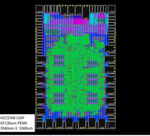
Penn is playing a leading role in the design of the front-end readout electronics for the entire silicon strip detector. Penn is responsible for the design of the HCCStar and the AMAC chips, and contributes to the design of the ABCStar:
- ABCStar (ATLAS Binary Chip): wire-bonded to 256 channels on the silicon strip sensor, finds clusters.
- HCCStar (Hybrid Controller Chip): builds events from 10 ABCStars in the barrel, and up to 11 in the endcap.
- AMAC (Autonomous Monitor And Control Chip): controls low voltage to the electronics, controls high voltage to the sensor, and monitors environmental conditions including voltages, currents (from tens of nanoAmps to tens of milliAmps), and temperature.
The first star prototype readout chips, developed during 2017-18 and tested during 2018-19, have a dedicated connection from each ABCStar to the HCCStar in order to support higher trigger and readout rates. These star chips support full detector readout with a single level trigger scheme with 1 MHz L0 rate, and also a multi-level trigger scheme that has a 4 MHz L0 rate with 600 kHz full readout at L1 and 400 kHz regional readout. Detector installation requires 233,856 ABCStars, 25,536 HCCStars, and 17,888 AMACs, though about 30% more chips will be fabricated to account for component and system assembly yields.
Validation of the chip design requires close collaboration between experts in the electronics and instrumentation group and the Penn ATLAS group. One particularly useful tool is cocotb, a Python interface to control standard RTL simulations (like Cadence). This is a lot easier to learn than System Verilog! This allows graduate students and postdocs to write code in Python to test the operation of the chips under realistic operating conditions (trigger rate, occupancy) as well as stress tests (trigger bursts). Further, it allows us to construct key tests of a barrel readout hybrid with the HCCStar connected to 10 ABCStars and the endcap hybrids with each HCCStar connected to up to 11 ABCStars. All of these validation tests can be run nightly (continuous integration) to check the effect of design changes during development. After fabrication, the chip design can be tested using single-chip device-under-test boards in the lab at Penn. Wafers containing hundreds of chips can be tested in a wafer probing station at Penn, where the validation tests developed above have been adapted for this purpose. Last but not least, the single-chip device under-test boards need to be able to operate in a high radiation environment, with tests done at irradiation facilities at Brookhaven for total ionzing dose with exposure to an intense Cobalt-60 source, at TRIUMF in Canada in a 480 MeV proton beam for single event effects, and at Louvain in Belgium in heavy ion beams, also for single event effects.
In 2020, the preproduction chips (5% of the production total) will be fabricated and tested. In 2021, the production chips will be fabricated and tested. The construction of the barrel staves and endcap petals will last from 2021 to 2024. Penn expects to contribute to stave assembly and testing at Brookhaven during this time, and detector commissioning at CERN as the strip detector is assembled on the surface.


Upgrade: Tracking for the Event Filter Trigger System
There is much more data from the ATLAS detector than can be feasibly stored long-term. Instead, a “trigger” decision is made very quickly in order to select the data that appears most interesting. The challenge of any trigger system is to choose these most interesting collisions using a limited amount of information processed in a very short time. The HL-LHC trigger system is significantly more difficult because the collision rate will increase by a factor of 5 from the Run-2 (2015-2018) rate. The number of collisions in each beam crossing (“pile-up”) will increase correspondingly from about 40 to 200 at the HL-LHC. Due to the much larger number of particles traversing the detector, there is confusion about which collision a particle comes from.
Of order 1,000 charged particles will emerge from each beam crossing (every 25 ns). The new silicon pixel and silicon strip detectors will provide measurements of where each particle is as they cross the sensors, but which particle each measurement (called a hit) comes from is not known. This results in a massive computation challenge. A pattern recognition process has to figure out which of the hits are due to the same charged particle. In order to use the charged particle tracking in the trigger decision, this has to be done at a very high rate. Specifically the baseline plan is to support 1 MHz of regional tracking, plus 150 kHz of high resolution full-detector tracking. Several options for this computation are being pursued. A team from Penn (Elliot Lipeles, Christian Herwig (2019), Ben Rosser (2021), Riley Xu, and Avi Kahn) are pursuing an option based on using FPGA processors as an alternative to a conventional CPU. This work includes algorithm development and simulation, and also firmware development.